Monday, 7 August 2023

Classic Sennheiser HD480 Headphone earpads

I have a pair of Sennheiser HD480 headphones, back when new they were "good HiFi".  

But the foam inside the earpads has disintegrated over time, and spares are difficult to find.  Canford Audio will sell a pair of their own design, but unfortunately as Canford are primarily a business supplier, they have minimum order value, a postage charge, etc.. so, unless one is shopping for other things they carry, one set of ear pads ends up costing over £50!


Disintegrated foam from the earpads


However, there is a way to fix them....  and its very very cheap.... 

wadding, not the easiest thing to photograph!

Quilting wadding.   Available from shops which sells supplies for quilting, and one needs a small piece of offcut of approx 10mm thick (1/2 inch would be fine).   The material I have is a synthetic, very open weave.   


Dismantle the headphone - run a finger nail around the metal trim ring behind the earpiece, and the trim piece and earpad will pop off.  Brush or gently hoover the remains of the foam from the earphone, and remove it from the mesh fabric cover.   

Use the metal trim piece as a template, and use a pen to draw round its outer edge on the wadding.  Then cut out with scissors to make a circle.  Its not precision cutting, just near-enough.  

Earphone, trim ring, and earpad with new wadding inside.


Push the round piece of wadding into the earphone mesh, running finger around a few times so it seats neatly.   

Refit trim piece and earpad to earphones by gently clicking into place.  Probably need to work around the rim a few times to get it to seat.   

HD480's with newly repadded earpads

I'm very happy with the result.    And having seen how the earpads are constructed, a replacement cover fabric doesn't look that hard....  As I'm pushing 60 my hearing isn't what it was when the phones were new, but such repairs mean these have a continued life. 


Monday, 20 February 2023

2mm conversion of NGS Hunslet

I've been looking at how to convert the N Gauge Society's Hunslet shunter to 2mm finescale for quite a while.  

Superficially it looked easy - same bearings in split frame as Bachmann have used in several of their smaller steam shunters, such as the Jinty and 57xx.    But, there were a few "gotchas" to catch those who might rush in.   The main one being the very tight clearance between a spur gear in the mechanism and one of the axles.  That meant the usual 2mm finescale parts for the Jinty conversion wouldn't fit without modification.  The muff connecting one axle needs to be thinned quite considerably, to less than 2mm O/D (when its got a 1.5mm hole inside it, that means a very thin wall).   Its possible if you have a lathe, and might be possible with care by holding a muff in a minidrill and filing/sanding the muff down to size (a sliding fit axle inside the muff stops it deforming).  In the photo below, the left side of the muff has been reduced from the nominal 2.3mm diameter of the right side: 


With that step out of the way, the rest is "normal conversion" - coupling rods to make (or reduce the hole size in the N gauge rods), and drop in the wheels.  


The other approach is to finescale the supplied wheels.  This is relatively simple to do for the lathe owner, the wheels are brass, so machine easily.  Reduce the flange height from 0.7mm to 0.5mm, and shave about 0.4mm off the back of the wheel, then gently round the edge of the flange with a file whilst the wheel spins in the lathe.  The hardeset part of this job is work-holding:  I made a tool which centred the wheel precisely, provided a drive pin, and had a shaft through the axle hole to a clamping domed washer and nut (sounds more complex than it really is!).  
The N wheels have a back-to-back of around 7.3mm.  For 2mm finescale it needs to be 8.5mm, an increase of 1.2mm.  The re-profiling gets 0.4mm per wheel, so 0.8mm, but a further 0.4mm is needed by sliding the wheels out on their axles.  This is OK, but I felt it was better if the bushes were replaced with slightly wider ones to reduce the amount of axle side-to-side float: for which the conversion bushes to use 2mm Scale Association wheels are suitable if drilled out to 3.0mm.  (I made my own, but that was because I hadn't got any conversion ones to hand and have enough machinery to make them quickly).  


So, neither method is quite "drop-in", but both fairly simple.  

Below is some video on YouTube of one loco running through a 2mm turnout.  This had the wheels turned down.  I'll get round to uploading some video of one using 2mm wheels later.  


Friday, 5 March 2021

Zimo Swiss Mapping and Zimo Input Mapping

With DCC lighting and sound features becoming more complicated, setting up of how those lights and sounds are controlled seems to be causing difficulties.   So, a short article on how to set up lighting function mapping, and altering which function keys associate with sounds in Zimo decoders. 

For the lighting outputs, I'll use Swiss Mapping.  Not because the locos are Swiss, but because its a really powerful and flexible way of controlling lights.     To control which sounds (and any other features) are controlled by which function keys is done with Zimo Input Mapping.   I'm assuming the use of DecoderPro.  It can all be done with manual CV numbers, but it takes a fair bit of typing.

For the lighting, my example has a loco with four independent lights, in a typical diesel loco with a cab at each end.  

  • The decoder headlamp wire (white) is connected to a white lamp at cab 1. 
  • The decoder rearlamp wire (yellow) is connected to a white lamp at cab 2.
  • The decoder F01 output wire (green) is connected to a red lamp at cab 1. 
  • The decoder F02 output wire (brown) is connected to a red lamp at cab 2. 

And, I'd like the following function keys on my handset: 

  • F0 key (lights) turns on directionally correct white and red lights (ie. loco running light engine). 
  • F0 key plus F9 key, turns on directionally correct white lights (ie. loco pulling a train, so loco red not seen). 
  • F10 key.  This will over-rule F0 or F9.  F10 turns on red lights at both ends, regardless of direction (ie. loco parked, with red markers on both ends).  
And I'm using a Zimo decoder....

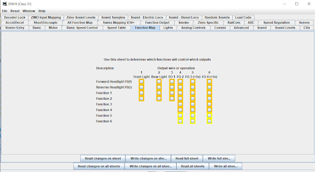
Step 1  Turn off the standard function mapping. 

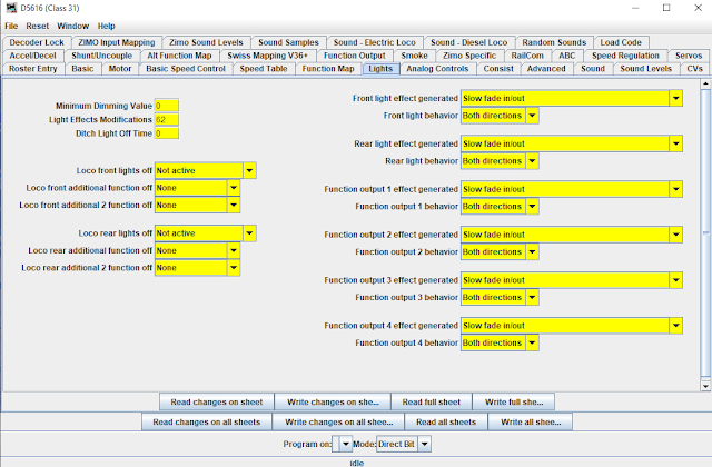
The standard function mapping is OK, but its constrained by the defaults set by the NMRA in the 1990's.  Newer methods offer more flexibility, so begin by turning off the old defaults.  Then, check that all the outputs (in the Lights pane) are set to "both directions".  


Default settings in decoder, turn these all off and write the changes to decoder:


Default function mapping turned off

And check that the outputs on the "lights" panel are all set to "both directions".


Understanding Swiss Mapping Basics

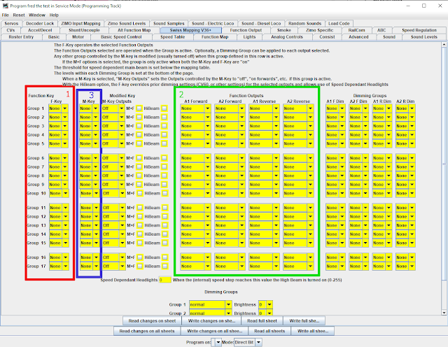
Swiss Mapping (from JMRI 4.23.3, earlier releases have fewer options)

The Swiss Mapping pane is quite complicated.  And the Zimo written manual is not well explained (and actually wrong in some details in the English translation). 
I have highlighted the three areas to consider on the DecoderPro Swiss Mapping pane as most important, in their order of consideration.  

Each row of the table is a "group".   A group is activated by a Function Key (outline #1).   When a group is active, it turns on some function outputs (outline #2).    So, at its simplest, select which function key is required as a F-Key (outline #1), and for that group, select the outputs to operate in the forward and reverse directions (outline #2)
If a particular situation requires more than two outputs in a particular direction, use a second group with the same Function Key value.  

Optionally, a group might Modify another group.  The group to be modified is entered in M-Key (modified key,  outline #3).    Typical (and default) entry of a value for the M-Key causes any groups which are operated by the M-Key to be turned off.   

The other areas are of lesser importance.  There are additional options around the Modify group (M-Key), and there are Dimming Groups (right hand side) which can dim the outputs selected in the Function Outputs (outline #2).  


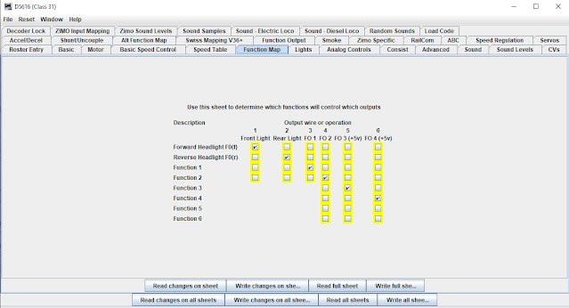
Setting up the loco lights in Swiss Mapping: 


In the example above, I have used four groups.  Taking each in turn. 

Group 1.  This is very simple, F-Key is F0.   The Outputs in the forward direction are FrontLight and F02,  which, earlier in the article, I said were connected to the White on Cab1 and the Red on Cab2.   The Outputs in the reverse direction are Rear Light and F01, which correspond to the White on Cab 2 and the Red on Cab 1.     So, function key F0 on the DCC Throttle will cause directional lights to work correctly on the locomotive.  

Group 2.   Referring back in the article, I wanted F9 to change the lights to be "white directional headlights only", for a loco pulling a train.   It should over-ride the F0 key which has both white and red lights showing.  
So, the F-Key is F9, to activate the group.   The required outputs are FrontLight (white on Cab 1) going forwards, and Rear Light (white on Cab 2) in the reverse direction.   To modify (turn off) the F0 key outputs, F0 is selected as the M-Key.    And, finally, to require both F0 and F9 to be turned on, the "M+F" tickbox is selected.  

Group 3.   Again, referring back, I wanted F10 to have "red lights all round", and this should override other light settings (F0 and/or F9).   
The F-key is F10.   The function outputs are F01 (red cab 1) and F02 (red cab 2), set in both directions.    To modify (turn off) the F0 outputs, the M-Key is set to F0.  (this means I've overridden F0). 

Group 4.  This completes group 3, where I was only able to override F0, but also wished to override F9 as well.   So, the F-Key to activate the group is F10 (same as group 3).    The modified key (M-Key) is F9.   As I've got all the required outputs in group 3, there is nothing to enter for the function outputs.  


With the above, and a little thinking about loco lights, it should be apparent that any arrangement is possible.  And slightly "oddball" loco arrangements become quite simple, such as a BR Class 86 or 90 which might be propelling a rake of coaches with a driving trailer at the front of the rake.  


In the final Swiss Mapping example above, I've added the use of Dimming to Group 3, to reduce the brightness of the outputs.   The outputs selected in Function Outputs are to be set to the dimming value in one of the five Dimming Groups (bottom of page).   In my example, Dimming Group 1 is set to brightness 10 (on scale of 0-31), and Dimming Group 2 set to brightness 15.   

Dimming Groups is a very flexible way of setting different levels for different outputs.  Five dimming groups should cover most requirements.  


Zimo Input Mapping  (Zimo Sound decoders only)

One common annoyance faced by users of sound-equipped locos is that the sounds are on the "wrong" function keys.   That might be because two different sound creators use different defaults, or because some of the sounds are really important for the particular layout, but others are not needed.   

Zimo Input Mapping allows an end user to move any "internal function key" to any desired actual function key.    So, an end user can have all their locos with the same function keys for similar sounds, rather than trying to remember where a function has been moved.   Thus, I might want to move a particular horn to a low function number, and another sound to a high function key.   And, I might want to move the sound on/off from F1 to a less frequently used key, thus freeing up F1 for something used more regularly.  


In my example above, I've decided that the sound which was on F6 when supplied isn't very important to me, so I've moved the Internal F6 to F23.   And, I've decided that the sound which was on F16 should be put on F6 where it is more accessible to me.  

It is legal to arrange direct swaps,  thus Internal F5 moved to F15, and Internal F15 moved to F5.   And more complex circular swaps may be possible (I have heard reports of some circular swaps not working).  

Note that the Input Mapping will also move other elements, such as Functions (lights), and speed settings (such as yard mode).  


Sunday, 11 June 2017

More stay-alive, back with the Class 02

Some time ago, I reported on fitting ceramic stay alive capacitors to my little class 02 shunter.   Subsequently I found out about the performance drop-off in ceramic capacitors near their rated voltage, and that means their performance for stay alive isn't as good as one might hope. 

So, mindful of that,  I've replaced the stay alive unit in the 02.  Out with the ceramics, and replaced with four 220uF, 16v rated Tantalums.   Those are fitted in both cab-sides, two capacitors to each side, so the cab-light in the loco had to go (but it didn't look particularly good, so its main function had been to test whether the stay-alive was working !). 

Net result, about 1/4 of a wheel turn without power at moderate speeds, far more than what's needed to get over a spec of dirt.   And, that's made me think about the DY1 shunter I built over a dozen years ago, and about finding space in the cab for capacitors in that loco. 

Saturday, 30 July 2016

More stay alive experiments

Prompted by a posting on the MERG forums about capacitor performance, I returned to the test bench to see what happens in the real world.

The MERG posting pointed to the performance of Ceramic capacitors as the applied voltage is varied.  At very low voltages (1 or 2v) they achieve their rated capacitance.  But, as the voltage rises towards the rated voltage, the capacitance declines quite dramatically.    In contrast, Tantalum capacitors have a nearly flat graph, with full capacitance at their rated voltage. 

My use of capacitors in stay-alive devices uses capacitors at or near their rated voltages, so the ceramics used in earlier postings were 16v rated and are used at voltages of around 13v. 

A typical Tantalum capacitor is about twice the volume compared to a Ceramic for the same uF and same 16v rating.   So, with a given volume in a loco, one can fit twice the uF of Ceramics to a loco.

Which brings me to the test bench.   My 4mm Scale Y6 Tram loco, fitted with a Mashima motor, High Level gearbox, and underneath, an 0-4-0 with coupling rods linking the wheels.   It was built with a CT DCX75 decoder, and originally fitted with 22 of 100uF Ceramic capacitors. 

An equivalent volume is achieved with 6 of 220uF Tantalum capacitors, or 1320uF in total. 

This was tested on the bench, and appeared to show a small but significant increase in how far a wheel revolves when power is removed.  
So, the first conclusion is that for equivalent volume, the Tantalum capacitor performs a little better than the Ceramic.

The next test was to increase the Tantalums to 2200uF by using 10 capacitors.  On the track, this gives about 1/4 of a wheel turn without power at modest running speeds.  This is substantially more than the about 1/10th of a wheel turn which the Ceramics would show.    So, clearly for the same uF rating, the Tantalums work much better than the Ceramics, which is consistent with the maker's specification sheets of declining performance mentioned above.

Overall conclusion for model building - for the same unit volume, Tantalums work better than Ceramics.  For the same distance travelled, about 0.3 of the uF in Tantalum will give the same movement as 1 unit of uF in Ceramics.  Tantalums are cheaper and available from more suppliers than Ceramics.  So, I'll be using Tantalums first and only if stuck on awkward space going over to Ceramics. 

Sunday, 21 July 2013

Stay Alive Capacitors in 2mm Scale

The last post on this blog was about Stay Alive capacitors for DCC, and this is the same topic, only much smaller. 

At the 2mm Scale Association summer Expo in June 2013, I had a long conversation with Jens Emmermann.  He showed me some locos fitted with tiny ceramic capacitors, and reminded me to read Carsten Berger's Digital1001 website.

Carsten's site has diagrams of CT decoders, including the locations of the positive and ground solder pads.  It also retails ceramic capacitors and other small parts,  the capacitors are about half the price of buying through Farnell in the UK.

The ceramic capacitors are 16v rated, 100uF.  They are rectangular and measure approx. 2.6 x 2.6 x 3.4 mm.   Being rectangular, they can be assembled into larger rectangular blocks.

So, to my test loco.   A class 02 shunter, which is 45mm long over the buffers.  Inside the cab is a space of 8 x 8 x 4mm below one cab window.  This space had carried a lump of lead, but as the loco has a very heavy solid brass chassis block, the lead only made a small difference to total weight. 


A rectangle of nine capacitors, totalling 900uF, was assembled onto a piece of 0.3mm thick PCB.  The upper surface of the capacitors were linked with a strand of wire which helped solder flow between the capacitor poles.   A second small PCB was assembled with the charge/discharge diode/resistor components.  Following advice on Carsten's site, a 16v Zener diode was also fitted across the capacitors as an over-voltage protection device.


Having made the parts, they were wrapped in very thin paper insulation,  I use model making fine masking tape for this, slicing pieces to the required shapes.

The final part of the assembly is the difficult bit, soldering two wires to the back of a CT DCX75 decoder.  The insulated film on the rear of the decoder has to be cut away over the pads, and a very small soldering iron tip is required to solder to the pads.  I filed an old soldering iron tip to the required shape, and I use a temperature controlled iron.  I practised a few times on some scrap PCB. 

This image shows the location of the solder pads:
The positive pad is accessible, being at the edge of the decoder.   The negative is much harder, its small and in the middle of the board. 

I found making the connections onto the decoder to be very difficult, soldering under lots of magnification to see the parts clearly.   It needs very good light, careful fixing of wires so they don't move and a very steady hand.   In future I might pick a different decoder, the solder pads are in better positions on some of the newer and smaller DCX76 models.

The end result seems superb.   I can't actually measure the stay-alive time, but it feels like around 0.2 to 0.3 seconds of running.  The observed behaviour is that the loco doesn't stall on the first tiny spec of dirt on the track. 

And, if its possible to get effective stay-alive in such a small loco, there can't be many locos where it is "impossible".  It's just difficult due to the tiny size of the components.

Monday, 6 August 2012

Decoder Stay Alive, mixing Zimo and TCS

Over the last couple of years, I've fitted a number of locos with "stay alive" capacitors, as detailed in the Zimo decoder manuals.   At the weekend, I bought a TCS KA2 stay alive unit, and have tried it attached to a Zimo decoder.

Bottom line; it works well, keeping the loco running for 20 seconds or so, covering a yard of track with power disconnected !

The KA2 has two wires, blue (to decoder blue) and black/white striped, which goes to the decoder ground ("mass" on some Zimo diagrams).   Compared to the DIY circuit in the Zimo manuals, the KA2 appears to be lacking the inductor (for programming sound and changing firmware) and a discharge resistor.  The discharge resistor is probably a good idea, as the KA2 can keep the Zimo decoder memory running for more than five minutes - put a loco back on the track with its memory still alive, and it will run at the last setting it remembers !!

Internally, the KA2 contains a couple of diodes and a charging resistor (to limit in-rush current), and another component (probably inductor, not sure yet), plus six 1F capacitors rated at 2.7v in series.  This gives a total of 0.16F rated at 16v, which corresponds to the maximum track voltage which TCS recommend for the KA2.   If the shape is wrong, then the capacitors could be removed from the circuit and strung around in a different configuration.  
A DIY version would be possible if equivalently compact capacitors could be found from electronics suppliers - I've found US sources of these, but not yet identified an EU/UK source with modest postal charges. 

Overall, recommended in any loco which might have pickup problems assuming there is enough space for the stay alive unit.   Unfortunately, its usually the smallest locos which have pickup problems, and those often lack any space.

Friday, 24 June 2011

Bench for RSPB Flatford

I am a volunteer for the RSPB in south Suffolk and north Essex. Usually this involves site maintenance in large woods or on fields which are breeding areas for estuarial birds. But, this year has had an unusual project; making a wildlife friendly garden at Flatford.

The Flatford garden sits alongside the National Trust property at Flatford which is world-famous as the scene of the Haywain and several other Constable paintings.

One thing a garden which will get lots of visitors needs are benches. So, wanting something a little different, I produced this bench in the RSPB workshop using off-cuts of chestnut from other parts of the garden project (the chestnut is local, felled as coppicing to maintain a wood, so about as sustainable as it gets). The shape of the bench does not dictate how you sit on it, you can choose any direction of view. Some of the ideas came from a bench made by Trannon for a museum, though with many modifications to suit outdoor use and the locally available timber.


If the bench proves successful in the garden, I'll make a few more. The 2nd version will have some changes to the seat shape, though will keep the octagonal theme.

Thursday, 23 June 2011

YADCV ( Yet another DCC Coupler Video )

I've done another DCC coupler design, in a Farish class 14 diesel. This one is a commission installation for another modeller (like certain famous motor cars, if you have to ask the price, you can't afford it!)

This time the coils are within the N scale NEM coupler pockets, and the DG couplers are on the loco body. This makes maintenance very much simpler as the fragile parts are well protected and the mechanical parts are slightly modified standard aftermarket couplers. The couplers are "handed" to match the stock on the layout in question where DG loops are only fitted at one end of the stock. So, the loco has a normal loop at one end which can be lifted, and a "lifter" at the other which lifts the loop from a wagon off the loco coupler.

I'll post some drawings at some point, but a bit of video to illustrate how it all works. The loco is a Farish Class 14 diesel, with the wheels turned down and re-gauged to run on 2mm Finescale track. Chip is a CT DCX75.

Blogger's video feature seems to be broken, so I've had to put it on YouTube

Sunday, 14 November 2010

The train on line 1 is running itself....

A long time since the last posting, but here is a train one...

For the Warley show this year, I will have a demonstration on DCC and 2mm scale topics. This will include some basic issues, such as how to fit decoders in limited space, and some more advanced topics, such as train detection, interlocking, and automation.

The advanced topics are illustrated with a simple track arrangement which can be run automatically or manually. A fairly rough video is shown below (bring back the old version of Windows Movie Editor, it was easier than the current one !).


The automated shunting sequence includes careful buffing up to the train, and if the loco running has lights, these are switched on/off at appropriate times.


The train detection is through MERG DTC-8 detectors which register current in a track section. Those feed their output to a HDL LocoIO board, which places the information on a LocoNet network. From the network, information is picked up by other LocoIO boards (displays status on LEDs, etc), and via a computer interface, to JMRI. The LocoIO boards also provide input from the manual lever frame, and output to LED signals at the trackside and servo motor drivers to move turnouts.

JMRI provides the interlocking for the signals rules, an on-screen duplicate of the lever frame, and the automation scripts which send instructions to run trains, change signals and turnouts, alter functions on trains, etc.. The scripts respond to the state of the track detectors. JMRI can track a named train around the system, so it is known which train is in which section.

Train movement comes from a Digitrax Zephyr command station, which relays instructions from LocoNet to the track. It also offers the manual running controller.

A second manual handset, a Uhlenbrock Fred, provides a hand-held controller.


And, if any visitors turn up with an iPhone with the WiThrottle Application loaded, they are welcome to connect it into the system and drive the trains on their iPhone.

Sunday, 11 April 2010

Skiing; Skarheimen 2010

(With apologies to those looking for model railways; fair chance the next posting will be on model making...)

A hut-to hut tour through Skarheimen, March 2010. Weather mixed, good some days (hence pictures!), poor others.

Arriving at the first hut, staffed.


Start of long day climbing a 1750m peak.

Peak appears through light cloud...

Further up, peak is immediately above skiiers, still nearly 2hrs until the top. One to right heavily corniced.


View from the top; lake is around 800m below, mountain in far distance perhaps 70km away.


Unstaffed hut; home for two nights.

Staffed hut under spectacular rock edge. But weather not good !


Journey's end, the road in the valley with a bus stop !

Skiing; Kvitavatn 2010

Early February 2010, possibly the best weather I have ever had skiing in mountains; whole week of sunshine, good visibility and only one windy day. Long days of up to 25km and 1000m of climbing - no ski lifts if you want to get into the wilderness !


Wednesday, 27 January 2010

Using six outputs on Zimo MX620

I have a 2mm scale Class 24 diesel, fitted with a Zimo MX620. I wish to use all six of the outputs on the chip to drive various features; independent lights, working couplings, and I might use the last output for a cab light.

The standard Farish 24 comes with a circuit board for a six-pin (2 function) decoder, and took up all the top of the chassis. This has the lights paired front and back. So the board was replaced. I'll post a sketch of those new boards later, their main feature is a 2.2Kohm resistor on each function output to control the current to the LED lights at each end.

The Zimo MX620 has six function outputs. Four are normal 12v full current, and two are "logic level". Two of the normal outputs are on the wiring harness (or pins), and all the others are on solder pads at the other end of the chip (along with a "ground" or 0v, and another 12v (or blue) pad). The outputs Fo3 and F04 are enabled by a CV change; they have a lot of capabilities; Susi sound data output, Servo driver or normal function output.

The logic outputs are about 5v, and could drive a very small current LED. But, the wiring of the lamps in the class 24 make it difficult to connect; they are wired for a common positive supply.
So, it was necessary to make F03 and F04 drive a normal output. This can be done several ways, but this simple transistor circuit does the job nicely:


The only additions to the normal connection to a function output is the transistor, the 50Kohm resistor, and the connection back to the Ground Pad on the decoder.

In my case, I used the track pickup (decoder red wire) to provide the positive supply. I had to attach wires to the solder pads for ground and the Function output.

I built the circuit twice; once with big parts and using long leads from loco to a test board. The second circuit (used in the loco for real) is a few square mm of 0.3mm PCB with surface mount resistors, and transistor laying on its side with legs cut very short. Check all the resistances, etc. before hooking up to the decoder !

Sunday, 20 December 2009

Skiing in Dedham Vale


Dedham Vale is perhaps best know for the paintings of John Constable (Haywain, etc). Its a few minutes from my home, and for the first time ever I've been able to ski on the meadows leading down to the Stour. This meadow is on the north bank, Dedham church is visible in the background of the first picture. Sorry that the pictures are a bit blurry, there is only so much that a camera on a cellphone can do.


Tuesday, 24 November 2009

Couplings on 0-6-0T

This loco belongs to the East Anglian Scalefour group and is used on Coldfair Green.


I have fitted DCC controlled AJ couplings to the loco using my etched parts.

I built up the couplings as complete units on a piece of printed circuit board. This was then fitted to the loco using the chassis mounting screws. Wires from the board went up to the loco, via some small PCB plug/sockets which allow the couplings to be electrically removed.


Coupling in closed (normal) position. Some parts temporarily held with "whitetac", araldite (or similar) will be used when happy that no further adjustments are required.


Coupling in open position, with magnet clearly visible on bottom of flap.


Close-up of front of loco, counterweight is visible below buffer beam, but fairly unobtrusive. Loco now requires cosmetic 3-link or screw coupling elements to be hung alongside AJ wire.

Yes, I am bending AJ hooks the "wrong" way. I have started experimenting with Vincent de Bode's method which puts the double section downwards (the downwards part still pulls the train load). Vincent's method offers the possibility of finer wire (the train load is no longer taken by the 180 degree bend) which in turn means the wire can be shorter for the same degree of springiness. It also means that the lower tail of a coupling cannot catch on a burr (there is no cut at the lower edge). The "Vincent bends" are compatible with conventional couplers, so its possible to mix and match between different types. Its too early for me to tell whether I will swap over wholesale to Vincent's method, but it shows promise.

Thursday, 17 September 2009

Etched brackets for DCC controlled AJ's

I've just taken delivery of a sheet of etched bits for the DCC Alex Jackson couplings. There was a fair bit of interest in them at Scaleforum, and I will be ordering a batch of coils in mid October.

If anyone would like to experiment with these, get in touch. There are pictures of the prototype etches in a small 4mm scale 0-4-0 posted earlier. There is some video of the 2mm version in action, and a list of CV values on the 2mm Scale Association website.

One etch per coupling (more if you are creative with the parts).
Prices £2 each, 6 for £10, 12 for £20 (UK post free), 20 for £30 (UK post free). Small orders post is £0.50 in the UK.


The etch picture shows the components;
top left - box to hold coil for rotating Alex Jackson (and similar rotation designs). Approx 4mm cube with "ear" for rotating shaft above.
bottom row - three different flap sizes
top right - base for DG coupling (2mm/N)
centre right - tongue for DG coupling
centre top - alternative brackets to box for coil (for very tight places).


Folded up box with simple flap (no counterweight).


Folded up DG version.